Saturday 29 February 2020

Arduino based Car controlled/programmed by Android


Components:
1. Arduino Uno
2. HC-05 bluetooth
3. L293D shield
4. Android phone
5. Connecting wires

Do connections as shown below,


Arduino Code:

#include<SoftwareSerial.h>
#define m1_p 10
#define m1_n 11
#define m2_p 12
#define m2_n 13
#define TxD 9
#define RxD 8
String str = "0";
SoftwareSerial bluetoothSerial(RxD, TxD);

void setup() {
  pinMode(m1_p, OUTPUT);
  pinMode(m1_n, OUTPUT);
  pinMode(m2_p, OUTPUT);
  pinMode(m2_n, OUTPUT);
  bluetoothSerial.begin(38400);
  Serial.begin(9600); // Default communication rate of the Bluetooth module
}
void loop() {
  if(bluetoothSerial.available() > 0){ // Checks whether data is comming from the serial port
    str = bluetoothSerial.readString(); // Reads the data from the serial port
    //Serial.println("123");
   worker(str);
 }


void worker(String str) {
  for(int i=0;i<str.length();i=i+2){
    char action = str[i+1];
    int timing = int(str[i]- '0');
 //   Serial.println(timing);
//    Serial.println(action);
//    Serial.println(timing);
//    Serial.println(i);
    if(action=='F') {
      //put motor functions here
  //    Serial.println("front");
      motor(1,0,1,0,timing);
    }
    else if(action=='B') {
   //   Serial.println("back");
      motor(0,1,0,1,timing);
    }
     else if(action=='L') {
   //   Serial.println("left");
      motor(1,0,0,1,timing);
    }
     else if(action=='R') {
   //   Serial.println("right");
      motor(0,1,1,0,timing);
    }
     else if(action=='(') {
  //    Serial.println("loop");
      int j=0;
      int rec_e=str.indexOf(')');
      String sub = str.substring(i+2,rec_e);
      
      while(j<timing) {
   //     Serial.println(sub);
        worker(sub);
        j=j+1;
      }
      i=i+rec_e-2;
    }
    else if(action=='S') {
   //   Serial.println("stop");
       motor(0,0,0,0,timing);
    }
  }
}

void motor(int p1, int n1, int p2, int n2,int timing) {
  if(timing == 0) {
    digitalWrite(m1_p,p1);
    digitalWrite(m1_n,n1);
    digitalWrite(m2_p,p2);
    digitalWrite(m2_n,n2);
  }
  else {
    digitalWrite(m1_p,p1);
    digitalWrite(m1_n,n1);
    digitalWrite(m2_p,p2);
    digitalWrite(m2_n,n2);
    delay(timing*1000);
    digitalWrite(m1_p,0);
    digitalWrite(m1_n,0);
    digitalWrite(m2_p,0);
    digitalWrite(m2_n,0);
   }
}


Android APK:  link
Make sure you pair the bluetooth before opening the app, the bluetooth module name must be "HC-05" and baud rate should be 38400 in order to make this app work with arduino/bluetooth.

To know how to configure Bluetooth check here

Thursday 5 June 2014

Modified A-Star Algorithm

Modified A Star Algorithm 


For Processing IDE Program Code Click here

For PPT slides of the algorithm Click here


Thursday 29 May 2014

Albert Einstein's Theory of Relativity

This is such a wonderful video that explains the theory of relativity by Einstein...please do watch

Sunday 4 May 2014

TIC TAC TOE IN PROCESSING UNDER ANDROID MODE

Hello everyone!!!
I had a thought of developing an Android application for a long time. I created an application successfully and became little familiar now on how to create an android app using processing software.

Professional android apps are developed using eclipse, but it is very tedious for me to learn because of lack of knowledge in Java. My friend gave me an idea that we can create android apps using processing under android mode easily which uses basic C syntax. I tried it and became successful within a short period.

Refer the link below to learn android processing. I recommend it for developing simple to medium complexity android apps.

All you have to do is to download Processing software from the following link.

Then open processing, initially on the top right corner Java mode will be seen. We need to change to android mode to create android apps. I will show you the shortest way to create unsigned android app for the program written. Signed app can be created by following the steps available in the internet to distribute the developed app in Google Play (which I haven’t tried).

Click the Java mode on top right corner, from the drop down select add mode. Then install android mode from the newly opened window.


Now the top right corner will change to android mode. Write the code and select sketch à run in emulator. To run in emulator you have to install latest JDK, the steps to do it is given in processing website.


After selecting run in emulator, you can see some texts running on the console. After the “debug” text appear on the console, move few lines back to see the link which ends with .apk extension.


Copy the link and paste it in Run from start menu. Then a window opens where the apk file for the program exist. We can copy and install in android phone to run the app.


The code running in emulator


The unsigned .apk file to install in android phone is given below. 
https://docs.google.com/file/d/0BzTE0x13LEHYWUxUdmtmX2xHMzQ/edit


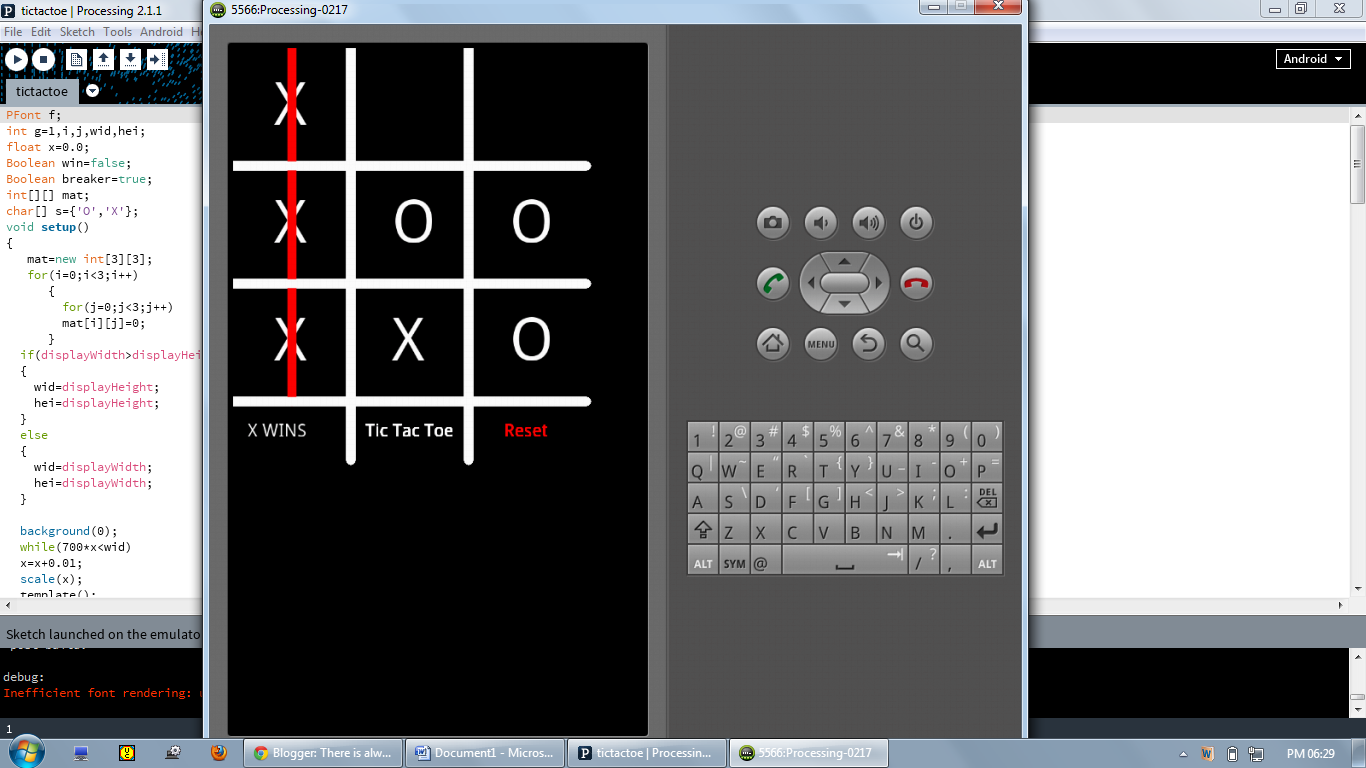
Code for the Tic Tac Toe application is given below.

PFont f;
int g=1,i,j,wid,hei;
float x=0.0;
Boolean win=false; 
Boolean breaker=true;
int[][] mat;
char[] s={'O','X'};
void setup()
{
   mat=new int[3][3];
   for(i=0;i<3;i++)
      {
        for(j=0;j<3;j++)
        mat[i][j]=0;   
      }    
  if(displayWidth>displayHeight)    // For scaling different screen sizes
  {
    wid=displayHeight;
    hei=displayHeight;
  }
  else
  {
    wid=displayWidth;
    hei=displayWidth;
  }
  
  background(0);
  while(700*x<wid)
  x=x+0.01;
  scale(x);
  template();  
}

void draw()
{
 scale(x);
  if(mousePressed && breaker==true)
  {    
    f=createFont("Georgia",100);
    textFont(f);
    fill(255);
    
    if(mouseX<2*wid/7&&mouseY<2*hei/7&&win==false)
    {
      text(s[g],70,130); //1st box
      mat[0][0]=g+2;
    }
    else if(mouseX<4*wid/7&&mouseY<2*hei/7&&win==false)
    {
      text(s[g],270,130);//2nd box
      mat[0][1]=g+2;
    }
    else if(mouseX<6*wid/7&&mouseY<2*hei/7&&win==false)
    {
      text(s[g],470,130);//3rd box
      mat[0][2]=g+2;
    }
    else if(mouseX<2*wid/7&&mouseY<4*hei/7&&win==false)
    {
      text(s[g],70,330);//4th box
      mat[1][0]=g+2;
    }
    else if(mouseX<4*wid/7&&mouseY<4*hei/7&&win==false)
    {
      text(s[g],270,330);//5th box 
      mat[1][1]=g+2;    
    }
    else if(mouseX<6*wid/7&&mouseY<4*hei/7&&win==false)
    {
      text(s[g],470,330);//6th box
      mat[1][2]=g+2;
    }
    else if(mouseX<2*wid/7&&mouseY<6*hei/7&&win==false)
    {
      text(s[g],70,530);//7th box
      mat[2][0]=g+2; 
    }
    else if(mouseX<4*wid/7&&mouseY<6*hei/7&&win==false)
    {       
      text(s[g],270,530);//8th box
      mat[2][1]=g+2;
    }
    else if(mouseX<6*wid/7&&mouseY<6*hei/7&&win==false)
    {        
      text(s[g],470,530);//9th box
      mat[2][2]=g+2;
    }
    else if(mouseX>4*wid/7&&mouseY>6*hei/7)//reset
    {
      for(i=0;i<3;i++)
      {
        for(j=0;j<3;j++)
        mat[i][j]=0;
      }
      win=false; 
      background(0);      
    }
    for(i=0;i<3;i++)
    {
      stroke(255,0,0); 
      if((mat[0][0]==g+2&&mat[1][1]==g+2&&mat[2][2]==g+2))
      {
        line(0,0,600,600);
        win=true;
      } 
      else if((mat[0][2]==g+2&&mat[1][1]==g+2&&mat[2][0]==g+2))
      {
        line(0,600,600,0);
        win=true;
      } 
      else if((mat[0][i]==g+2&&mat[1][i]==g+2&&mat[2][i]==g+2))
      {
        line(100+(i*200),0,100+(i*200),600);
        win=true;
      }
      else if((mat[i][0]==g+2&&mat[i][1]==g+2&&mat[i][2]==g+2))
      {
        line(0,100+(i*200),600,100+(i*200));
        win=true;
      }
    }
    
    if(win!=true)
    {
    g=g+1;
    if(g==2)
    g=0;
    }
    template();
    breaker=false;
  }
  if(breaker==false && mousePressed==false)
  breaker=true;
}

void template()
{
  stroke(255);
  strokeWeight(15);
  fill(255);
  line(200,0,200,700);
  line(400,0,400,700);
  line(0,200,600,200);
  line(0,400,600,400);
  line(0,600,600,600);
  f=createFont("Georgia",30);
  textFont(f);
  text("Tic Tac Toe",225,660);
  fill(255,0,0);
  text("Reset",460,660);
  fill(0);
  noStroke();
  rect(20,625,125,50);  
  f=createFont("Georgia",30);
  textFont(f);
  fill(255);  
  if(win==true)
  {
    text(s[g],25,660);
    text("WINS",50,660); 
  }
  else
  {
    text(s[g],25,660);
    text("'s Turn",50,660);
  }  
}


Saturday 5 April 2014

MICRO CONTROLLER BASED TIMER FOR LOAD CONTROL

Hello everyone, It has been a long time since my last post, I was a little busy with my final year project. In this blog I would like to share a project which I have already done a year ago as a mini project.


IMPLEMENTATION OF MICRO CONTROLLER BASED TIMER FOR LOAD CONTROL 

Project Overview
            The objective of the project is to switch on/off the load depending upon the timer value set. The design of circuit, simulation and creation of PCB is carried out using PROTEUS 7 professional software. The components primarily used are microcontroller (IC AT89c51), seven segment display, relay, switches & led’s etc.

This design works in 3 modes.
Mode 0: This is an ON timer. Load is ON initially; after Timer is started Load is ON till the timer value expires.
Mode 1: This is an OFF timer. Load is OFF initially; after Timer is started Load is OFF till the timer value expires.
Mode 2: This is an ON/OFF timer. Load is ON/OFF initially based on setting for type of repeat set, here the Load is ON and OFF alternatively based on timer setting for both operation.


Stages of Project Design
            The overall design of the project has been divided into two stages. They are described as follows:

Software design and simulation
            The code for performing the objective of the project is written in ALP (Assembly Language Programming). This code is compiled using Keil Vision. The µVision3 IDE is a Windows-based software development platform that combines a robust editor, project manager, and make facility. µVision3 integrates all tools including the C compiler, macro assembler, linker/locator, and HEX file generator. The developed circuited diagram is simulated using Proteus ISIS Professional. Then the hex file generated using keil µVision is loaded into the microcontroller ic using universal programmer. For performing the PCB design we use PROTEUS ARES.

Hardware Design
            This stage basically involves the connecting of all hardware components with each other. Intially the PCB layout is printed in a white sheet using laser printer. This printed circuit is deposited on the copper clad by ironing the white sheet on the clad. Then immerse the clad in the ferric chloride acid - the circuit tracks are not etched on the copper plate but only the non-inked exposed parts of the Copper clad. Now the components are placed on the PCB board and soldering is performed. After completion of interfacing, a trial run is done so as to ensure that all the components are working satisfactorily.

Block Diagram


Block Diagram Description
                        The microcontroller is connected to input output peripherals as shown in the block diagram. When the power is turned ON, the microcontroller and the load turns ON. Among the three modes, any one mode is selected using the input push button switch. After selecting the mode, the timing values are also given using the push button switches - the values that are given are displayed in the output seven segment display.

                        After all procedures, the start push button switch is turned ON and  the load is ON till the timer set value. When the timer value attains zero the load changes its present state.


Circuit Diagram (PROTEUS ISIS PROFESSIONAL)


PCB Design (PROTEUS ARES PROFESSIONAL) 


Steps to be followed for PCB design
  • Design the PCB in ARES professional
  • Take Laser printout of the layout.
  • In a copper clad place the printout and iron it for about 10 mins
  • Then drop the copper clad along with printout into a water bath so that the tracks are stuck to the copper clad firmly.
  • Remove the printout paper, now the copper clad will have the circuit tracks which are nothing but ink transferred from printout to clad
  • The tracks isolate the parts of the copper clad where we want tracks and other parts will be etched when the clad is dropped into Ferric chloride bath
  • Depending on the concentration of Ferric chloride acid the etching time varies
  • Now we will get the etched PCB, the ink is removed using thinner or kerosene
  • Drill holes in PCB at via points with 0.5mm drill bit.
  • Then solder the components optional Tin bath can be done for covering the track with Tin for ease of soldering. 

PCB Layout can also be designed using "Express PCB" software

I found it easy to design with it than with ARES.
Try with this also.


PCB LAYOUT printed using EXPRESS PCB

Construction & Working:

Construction
            The components in circuit shown are placed in the PCB board and soldered. 12V power supply is used for the operation of the circuit, 12 v for the relay and 5v for microcontroller and 7Segment LED regulated using IC7805. Crystal oscillator of 11.592 MHz is used a clock frequency. The push button switches and the seven segment display are connected as shown in circuit diagram. Here six push button switches are used .
1.      For incrementing the count value (INC).
2.      For decrementing the count value (DEC).
3.      For starting the operation (START).
4.      For confirming the value set (NEXT).
5.      For Repeat mode initial setting (ON/OFF)
6.      For resetting the controller.

Relay is interfaced with microcontroller using a transistor 2N2222 NPN, since each port pin cannot supply enough to drive the relay which needs around 100mA, we make use of external pull up even though each port pin of microcontroller has 10K internal pull up except port 0.

Thus from each port pin we can get a maximum of  0.5mA(since  I=5V/10K=0.5mA), in order to get 100mA to drive the relay we use a transistor that has href of 100, so that if input is 1mA the output current is 100mA amplified. So to get 1mA at base of transistor for obtaining required current output we have to add additional  0.5mA to the base this is done by using 10Kohms resistor and connecting in parallel to internal pull ups (since I=5V/10K=0.5mA), thus 0.5mA+0.5mA will give 1mA, transistor will amplify to 100mA so that we can drive the relay if the pin P2.7 is ON.


Softwares used for project design

  • PROTEUS ISIS PROFESSIONAL.
  •   Keil µ Vision3.

Work done using Proteus 7 professional

ISIS professional
  • Components for our project is placed in the workspace
  • They are interconnected as per the circuit desired
  • Microcontroller IC is linked with the Hex code generated from Keil uvision3 software
  • The whole circuit is simulated for any error.
ARES professional
  • The components used in the simulation of schematic is linked to the PCB design software i.e. ARES professional
  • The tracks are drawn for the circuit this is done easily by the guiding procedure followed by ARES which links with the circuit in schematic.
  • The final circuit is printed for making PCB


Work done using keil uvision3:
  • Code is written in Embedded C language for our project
  • It is then compiled for any errors and debugged
  • Then the Hex code for the program is generated
  • The Hex code is then linked to Proteus ISIS simulation.


Working
                 Initially, the output from all the port pins of the controller will be in high state i.e. 5v. First the operating mode of operation is selected using push button switches. Now the push button switches are operated in order to load the count value (values are displayed in the seven segment display). After pressing the start button the timer starts counting and resets, due to which load changes its state according to the mode of operation selected.

            The output is taken across pin no: 28 (P2.7). The output signal from this pin is amplified using a NPN transistor(2N2222) to drive the relay. So load changes its state according to the  from this pin, which is controlled by the timing value stored in the timer register.

STEPS FOR WORKING:
1. Select the mode of operation, viz. 0, 1, 2. This can be chosen using INC and DEC button.
2. Press NEXT button
3. According the mode selected enter the timer value for each digit of HH/MM/SS
4. Make use of INC and DEC button to choose a number between 0 to 9 for each of six digits in case of first two modes and 12 digits in case of repeat mode (mode 2) since it is having ON time and OFF time value to be set.
5. Press NEXT after choosing each digit for HH/MM/SS, which is displayed in 7 Seg LED
6. Then after setting the timer value press START button.
7. In case of mode 2 select ON/OFF, it is OFF the load first then ON the load type of operation by default, on pressing the ON/OFF button ON the load first then OFF the load type of operation is selected. This sequence will repeat forever.


COMPLETED PROJECT


To Visit the you tube link of simulated working Click here

To Visit the you tube link of real time working Click here


Program code:

#include<reg51.h>
#define side0 P0
 sbit inc=P2^0;
 sbit dec=P2^1;
 sbit onoff=P2^2;
 sbit next=P2^3;
 sbit start=P2^4;
 sbit relay=P2^7;
 void work(unsigned int);
 void delay(unsigned int);
 void converter(int);
 int x;


void main(void)
{
 int b;
 relay=0;
 x=0;
 while(1)
 {
 side0=~0x9c;
 delay(50);
 for(b=0;b<3;b++)
 {
 converter(b);
 while(inc==1&&dec==1&&next==1);
 if(next==0)
 {
 while(next==0);
 work(b);
 }
 if(dec==0)
 b=b-2;
 while(inc==0||dec==0);
 if(b==2||b==-2)
 b=-1;
 }
 }
 }


 void work(unsigned int f)
 {
  int c,d,e=0,b[15],e1,a1,d1,b1,z,val[3];
  x=0;
  if(f==0||f==1)                          //on or off timer value initialize
  {
  for(c=-1;c<10;c++)
  {
  converter(c);
  while(inc==1&&dec==1&&next==1);
  if(next==0&&c!=-1)
  {
  while(next==0);
  b[x]=c;
  x=x+1;
  c=-2;
  if(x==6)                                 //to break from for loop
  c=11;
  }
  if(dec==0)
  c=c-2;
  while(inc==0||dec==0);
  if(c==9)
  {
  c=-2;
  }
  }
  }
 
  else if(f==2)                                                    //repetition timer value initialize
  {
  for(d=0;d<=7;d=d+7)                                   //b[0]-b[5] & b[7]-b[12]
  {
  x=0;
  for(c=-1;c<10;c++)
  {
  converter(c);
  while(inc==1&&dec==1&&next==1);
  if(next==0)
  {
  while(next==0);
  b[x+d]=c;
  x=x+1;
  c=-2;
  if(x==6||x==13)                                 //to break from for loop
  c=10;
  }
  if(dec==0)
  c=c-2;
  while(inc==0||dec==0);
  if(c==9)
  c=-2;
  }
  }
  }


  while(1)
  {
  if(f!=2)
  {
  while(start==1);
 relay=1-f;
 val[0]=((b[0]*10)+b[1])*60*60;
 val[1]=((b[2]*10)+b[3])*60;
 val[2]=(b[4]*10)+b[5];
 for(e1=0;e1<3;e1++)
 {
 for(a1=0;a1<val[e1];a1++)
 {
 for(d1=0;d1<10;d1++)
 {
 for(b1=0;b1<15500;b1++);
 }
 }
 }
 relay=~relay;
  }


 else if(f==2)
 {
 converter(e=0);
 z=0;
 while(start==1)
 {
 if(onoff==0)
 {
 z=1;
 converter(e=1);
 }
 }
 while(1)
 {
 relay=z;
 val[0]=((b[0]*10)+b[1])*60*60;
 val[1]=((b[2]*10)+b[3])*60;
 val[2]=(b[4]*10)+b[5];
 for(e1=0;e1<3;e1++)
 {
 for(a1=0;a1<val[e1];a1++)
 {
 for(d1=0;d1<10;d1++)
 {
 for(b1=0;b1<15500;b1++);
 }
 }
 }
 relay=~relay;
 val[0]=((b[7]*10)+b[8])*60*60;
 val[1]=((b[9]*10)+b[10])*60;
 val[2]=(b[11]*10)+b[12];
 for(e1=0;e1<3;e1++)
 {
 for(a1=0;a1<val[e1];a1++)
 {
 for(d1=0;d1<10;d1++)
 {
 for(b1=0;b1<15500;b1++);
 }}}}
 }
 while(start==1);
 while(start==0);
 }
 }


void converter(int d)
 {
 if(d==0)
 side0=~0xfc;
 else if(d==1)
 side0=~0x60;
 else if(d==2)
 side0=~0xda;
 else if(d==3)
 side0=~0xf2;
 else if(d==4)
 side0=~0x66;
 else if(d==5)
 side0=~0xb6;
 else if(d==6)
 side0=~0xbe;
 else if(d==7)
 side0=~0xe0;
 else if(d==8)
 side0=~0xfe;
 else if(d==9)
 side0=~0xf6;
 else
 {
 if(x==0||x==7)//hours
 side0=~0x6e;
  else if(x==2||x==9)//min
 side0=~0x2a;
  else if(x==4||x==11)//sec
 side0=~0xb6;
 delay(50);
 side0=~0x00;
 }
 }

void delay(unsigned int n)
 {
 unsigned int i,j;
 for(i=0;i<n;i++)
 for(j=0;j<2000;j++);
 }


11. Conclusion & References
                      
               The Microcontroller based timer for load control is one of the project which will be very useful for home as well as office applications to reduce the burden of the people to switch ON and OFF the appliances around them. Once the timing is set the operation is continuous and reliable.


If you have any doubt regarding the project feel free to comment below